1 Leveling the transport system to the solder wave
2 Evaluation of smooth solder pump performance
3 Adequacy of flux distribution and thickness.
This unique method of topside observation of the actual wave-to-board" contact
provides added opportunity for precise analysis of your own particular process. LEV CHECK
is helpful in identifying proper angle of contact, flux and / or oil intermix,
displacement, flushing action, direction of solder flow, and meniscus velocity at the
break away "trailing edge" of the solder contact. It also allow visual
observation of wave impingement on board surface and turbulence.
How to
Use
LEV CHECK
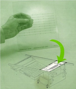
Solder Wave Gauge is easy to use. The basic principle is to simulate all condition as
close as possible to your own production process. This means fluxing, preheating, conveyor
speed etc. to be kept the same as if soldering actual printed wiring boards. Simulating
these conditions will demonstrate visibly how your process works. Place glass with grid
pattern side facing up.
Flux Application Visual observation of the pattern of the flux wave or foam head through
the transparent LEV CHECK gauge monitors adequate, uniform quantity of flux application.
Subsequent action to air knife or brush control can be monitored and precisely adjusted to
prevent wasted and fire hazard of flux spillage on preheaters.
Preheater
Effectiveness can be observed for controlled evaporation of flux solvent prior to entry
into hot solder wave
Evaluation Of
the solder wave may be done into two different ways.
1 Dynamic Test is a fast "qualitative" method
performed by simply running the LEV CHECK gauge across the entire soldering operation at
the same continuous rate as a standard production PWB.
Observe uniformity of solder sweep across entire width of contact surface. The total area
of glass contacted by the solder wave illustrates the immersion depth of the board in the
solder. Trailing edge at break away of solder from gauge should show a minimum of
1/32" of flux line - a good indicator for reducing tendency for icicling. The
velocity of meniscus of solder draining should be greater than the velocity of board over
the soldering machine. Simple observation will allow swift adjustment of conveyor speed or
wave height. The "float effect" due to impingement action of solder wave and
thermal gradient produced on the board can be observed and controlled by fixture
adjustment, conveyor speed and temperature of solder.
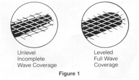
2 Stationary
Test is stopping the conveyor with the LEV CHECK gauge centered across the solder
wave within the marked gauge lines. This test is "quantitative" as now the
precise contour can be seen as well as the total area of contact with the solder. If the
width of the wave is not uniform at each end as line up by the gauge lines as seen in
Figure 1, then leveling adjustment may be made while the LEV CHECK gauge is still in
place.
To determine
contact time, place gauge on conveyor using normal speed. Measure width of wave as glass
is centered on solder. Conveyor may be stopped briefly to obtain width. Contact time and
the resulting time/temperature ratio can be calculated by multiplying thickness of wave
observed on gauge by 60 sec/min. and dividing this product by conveyor speed in inches per
minute.
Effective
action of flux and solder depend upon minimal time/ temperature of solder contact. On the
other hand, a long dwell time at too high temperature may damage both thermal sensitive
components as well as delicate board substrates.
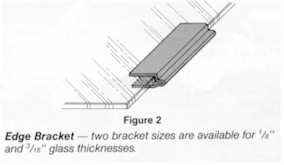
The purpose of
the edge brackets is to set the bottom of the glass plate at the same level as the
bottom of the PWB (as shown in figure 2.) The edge brackets are made from 0.020"
titanium and are sold for specific glass thickness 1/8" or 3/16" and come in
sets of four to a package.
This tempered
glass panel has been designed to withstand normal heat of soldering for short duration.
The glass will not tolerate thermal shock as well as a laminated epoxy glass
substrate and certain precautions should be taken to prevent accidental breakage. Do not
force the glass into a fixture or mount it too tightly. Expansion from heating may
increase risk of breakage. Soldering temperature of 500-525 degrees F will not
adversely affect the LEV CHECK. Normal transport speeds across preheaters are acceptable,
and stationary dwell time on wave for observation is allowable for up to 30 seconds.
Temperature above 525 degrees F require extra precaution to reduce the sudden build up of
uneven thermal strain on the glass. At these higher temperature the use of a slower speed
across the preheaters is suggested. Do not hold the glass panel stationary
on the solder wave longer than thirty seconds.
When
to Use
How often the
LEV CHECK gauge is used depends on the degree of the process control you need to satisfy
you company's quality requirements. Time required for the dynamic test as a routine
quality check of the wave process is not much longer than the cycle time of soldering a
standard production board. This makes frequent monitoring easy and inexpensive without
costly delays of production interruption.
As a general
rule, the gauge should be used a the start of each shift. If many different sizes of board
are used or the wave parameters are changed an additional test is recommended.
Caution
Do not expose
glass to soldering heat without flux and preheat cycle.
Do not position gauge so glass extends beyond width of solder wave. Choose gauge or wave
width so that solder spreads completely across the width of LEV CHECK gauge.
Position LEV CHECK for use with marking side up.
The LEV CHECK Solder Wave Gauge is tempered borosilicate glass specially designed to
withstand the extreme thermal shock of a typical 525 degrees F solder wave. Do not try
this with ordinary glass.
Although it has good mechanical strength and excellent impact properties, (5 times as
strong as standard annealed glass) it is sensitive to mechanical stress on the corners and
edges. Do not force it or mount tightly in a rigid holding fixture. Expansion from heating
may cause unusual mechanical stress and together with the thermal shock increase the risk
of breakage. Because of the nature of this tempered glass, if breakage should occur. the
glass may shatter completely into "gravel type" particles not needle sharp
silvers like ordinary window glass. Any glass particles will float on the solder surface
and are readily removed.
Use all normal safety precautions while observing LEV CHECK including safety glasses.
Cleaning
and Storage
Allow LEV
CHECK gauge to cool before handling. Because it is thicker than a production PWB, it will
take more time. Do Not Chill the hot glass suddenly. Allow it to air cool. Clean off
excess flux remaining with suitable solvent. Dry and replace glass gauge in its
protective bag and envelope. Store LEV CHECK carefully. It is more likely to be
broken through careless handling than from heat. Bookcase or file drawer storage is
advised . Use the shipping box for convenient storage.
Stock Standards
Model LC810
8"x10"x1/8" 1/2" parallel gauge lines
Model LC1510 15"x10x1/8"
1" square grid lines
Edges Brackets
Model LC 125 adapts 1/8" thick
glass to 1/16" fixture.
Model LC 187 adapts 3/16" thick glass to 1/16" fixture.
|